What EMC regulations do you need to think about when designing with PCAP touchscreens to ensure your product passes first time?
Electromagnetic compatibility is all about ensuring that individual electronic devices do not prevent each other from working correctly when being used in the same vicinity. The principle is easy enough to understand: nobody wants effects like power-supply noise from a computer interfering with their favourite shows on their TV or mobile screen. More importantly, disruption of critical equipment like a dialysis machine, emergency-services radio, or air-traffic control monitor is more than just annoying – it could be life-threatening.
The more mission-critical or safety-critical the equipment, the greater the required level of immunity to external noise. However, designing for higher levels is more complicated if the user interface is to feature projected-capacitive (PCAP) touch – a touchscreen may be needed to simplify splash-proofing for use in an industrial environment, or ensure easy wipe-clean hygiene for a medical device. After all, PCAP sensing works by detecting the disturbances that result from the user touching the screen. The controller must be sensitive to detect the touch, and its position, but mustn’t wrongly interpret noise signals to be user commands. These noise signals could originate from outside the equipment, or from internal subsystems such as switching power converters.
The international standard that governs testing for immunity to noise conducted into equipment through cables and connections is IEC 61000-4-6. In Europe, this has been adopted as EN 61000-4-6, and similar regional variants are in place in other markets such as the US/Canada and China.
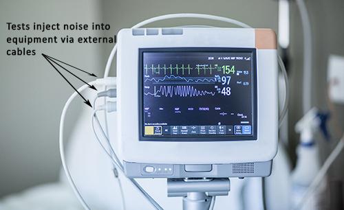
The tests specified in the European standard require a disturbance signal to be applied in common mode to any external cables that are connected to the equipment in normal operation (figure 1).

The test is repeated through the frequency range from 150kHz to 80MHz, and the equipment behaviour is monitored to ensure the noise signal does not cause malfunctioning.
|
Level |
UO dB |
UO |
IC Grade |
|
1 |
120µV |
1V |
Consumer-grade |
|
2 |
130µV |
3V |
Industrial-grade |
|
3 |
140µv |
10V |
HIgh-end |
The table describes the magnitude of the test signal, UO (nominal voltage to earth), that can be applied. The appropriate level for any given type of equipment is not specified in the standard but instead depends on the product category and target market.
The performance of the controller’s embedded touch-detection algorithm influences whether it can distinguish between a touch-related disturbance and unwanted electrical noise. Most consumer-grade ICs can pass Level 1 tests, which specify a disturbance signal amplitude of 1V. An industrial-grade or high-end controller is usually needed to pass EN 61000-4-6 tests with a Level 2 or Level 3 noise source. If your product fails the test at the level you require, relatively simple changes like re-optimising the controller’s firmware are sometimes successful, but not always.
Other factors such as board layout, interconnect lengths, and the design and placement of EMI filters all have an influence over immunity to conducted noise, but making significant changes to any of these late in the project can be expensive and may even delay your product’s entry to the market. Moreover, each additional session needed at the test house can involve further expense and waiting. So, it’s always best to establish the level you need to reach, and the design approach you will take to achieve it, as early as possible in the project to get to market at the right time and the right price.


